


Set out a decking frame by establishing the finished deck dimensions and board direction, then marking the joists, supporting beams and foundations from a checked design. Confirm the perimeter, diagonals and levels before constructing the supports.
Board support spacing and structural spans answer different questions. Both need checking before the layout becomes a frame on site.
A decking frame starts with the surface you want to create, but its layout must also explain how that surface receives support. Board direction, perimeter details and changes in level all influence the structure beneath.
This guide uses the original drawings for a small square deck to explain the setting-out process. They illustrate the arrangement of components; timber sizes, spans, connections and foundations still need specifying for the actual project.
Start with the finished deck
Decide the overall deck size, board direction and finished surface height before marking the joists. Include steps, fascia, picture-frame borders and any board-end joints, because each can change where support is required.
For a simple straight-board layout, the main joists usually run perpendicular to the boards. Diagonal boards or decorative patterns can change the required support spacing and introduce additional framing.
A picture-frame border or change in board direction needs its own support detail. Agree the surface pattern before constructing the frame, rather than trying to add support after the boards arrive.
Understand joist centres, beam spacing and spans
The distance between two joists determines how far the deck boards span. The distance between the joist’s supports determines how far the structural timber spans; these measurements are not interchangeable.
| Measurement | What it means | What determines it |
|---|---|---|
| Joist centres | Distance from the centre of one joist to the centre of the next. | The board manufacturer’s support requirements and the structural design. |
| Joist clear span | Unsupported distance between the faces of the joist’s supports. | Timber dimensions, grade, loading and the applicable design or span table. |
| Beam centres | Distance between the centre lines of neighbouring beams. | The joist support arrangement and frame geometry. |
| Beam span and post spacing | The beam’s support distances. Post centres and clear span differ where supports have width. | The beam section, loading, support arrangement and connection design. |
If a board manufacturer permits a maximum of 400 mm joist centres for the proposed installation, that controls board support spacing. It does not mean the joists can span any distance between beams.
Read the definitions and assumptions accompanying a span table. Use the actual timber dimensions and specified grade, and establish whether a figure refers to clear span, effective span or support centres.
Where do the beams, posts and foundations go?
Position the beams so that the joists remain within their permitted spans. Then establish the support positions along each beam from the beam design, rather than copying the joist spacing.
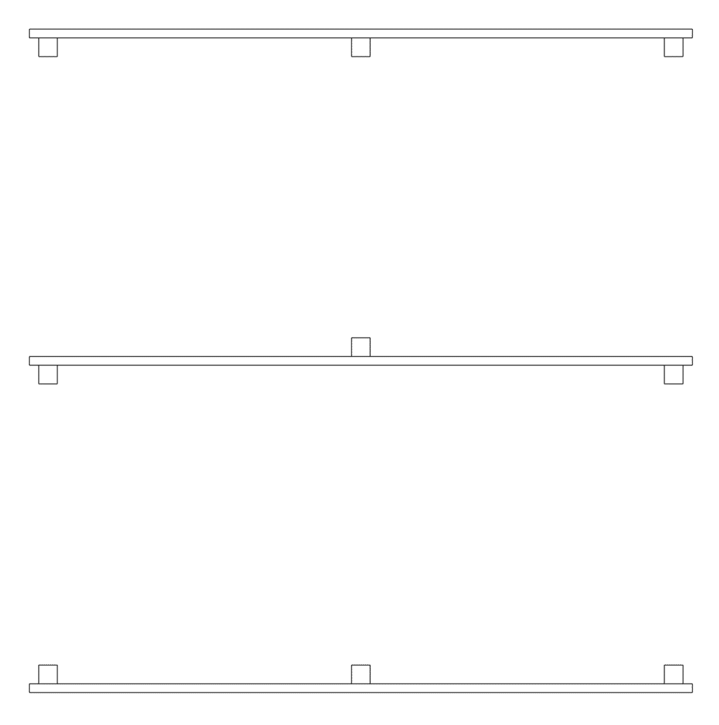
Beam spacing affects the area of deck loading carried by each beam. A centre beam may receive load from joists on both sides, so it can have different requirements from an edge beam.
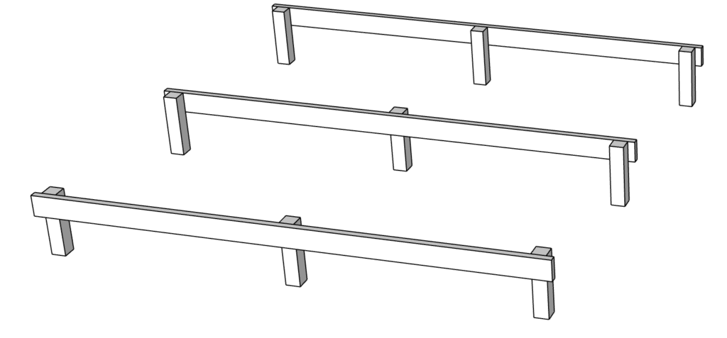
Each support needs a suitable foundation and a specified route for transferring the load into the ground. Ground conditions, drainage, existing services and access can influence the support design and its position.
Should joists sit on top of beams or between them?
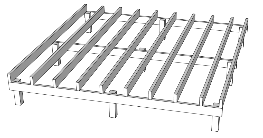
Joists bearing on top of beams
This arrangement stacks the joists above their supporting beams, increasing the total frame depth. Check bearing, restraint, connections and any cantilever detail as part of the design.
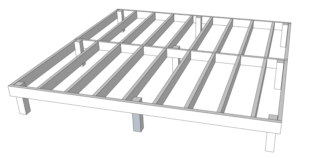
Joists meeting the beams at the same level
A flush arrangement can reduce frame depth, but each joist end still needs a suitable connection. Specify the hanger or other designed support, together with its fasteners and exterior suitability.
Our guide to connecting decking joists to beams explains the distinction between bearing support and a connection carrying the joist-end load.
Read the original decking frame example
This example has a finished deck size of 3,600 × 3,600 mm. The retained dimensioned drawing shows the structural frame measuring 3,550 × 3,550 mm, with an example joist spacing of 400 mm centres.
The difference allows for fascia boards around the perimeter and a slight decking-board overhang. Together, those perimeter details extend the finished deck 25 mm beyond each opposing frame edge, bringing the overall dimension to 3,600 mm.
That 25 mm is the combined perimeter allowance, not a prescribed board overhang. Set the fascia position and board projection to suit the selected products and their installation requirements.
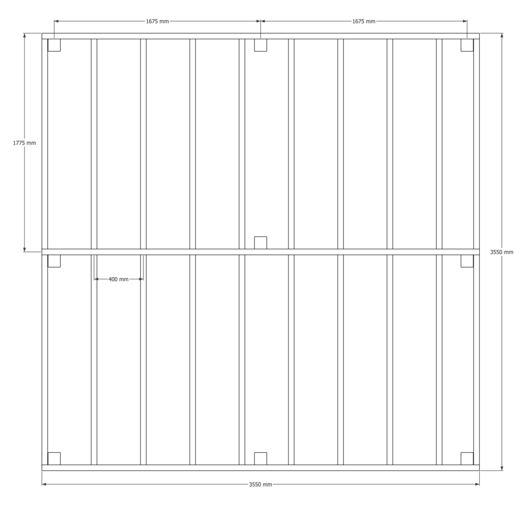
The frame size alone cannot establish suitable timber sections or post spacing. Record actual timber dimensions, strength grade, durability treatment, design loads and connection details alongside the layout.
Specify timber durability and preservative treatment for the actual exposure and intended service life. Treatment and strength grading serve different purposes, so both belong in the specification.
How to set out the decking frame on site
- Establish a reference line. Choose a reliable baseline and a fixed height datum so that the footprint and levels relate to the same references.
- Mark the perimeter. Set out the frame corners from the agreed dimensions, allowing for the separately specified board edges and fascia.
- Check for square. Confirm opposite sides and diagonals against the drawing. For a rectangular footprint, equal diagonals combined with the correct side dimensions provide a useful check.
- Mark beam and support positions. Distinguish centre-line marks from timber faces, checking ground conditions and service locations before excavation.
- Confirm the height build-up. Allow for boards, joists, beams, connections and the designed ground clearance. Check thresholds, drainage and access before fixing levels.
- Mark joist positions and extra supports. Include board ends, borders, steps, blocking and changes of direction. Measure consistently from a common reference to limit accumulated errors.
- Recheck the assembled frame. Confirm dimensions, diagonals, levels, support spacing and connections before the boards conceal the structure.
Which standards and guidance apply?
Eurocode 5 provides the timber structural design framework, used with the applicable UK National Annex and supporting guidance. Planning and Building Regulations requirements are separate matters and depend on the location and project.
BS 5268-7.1:1989 is withdrawn. Its historical calculations should not be presented as a current decking regulation or labelled as Eurocode 5.
Use applicable structural design information and span tables with their stated assumptions. Where the proposed arrangement falls outside those assumptions, obtain a design for the actual structure.
Checks before constructing the frame
- Finished deck dimensions and frame dimensions are recorded separately.
- Board direction, joints and perimeter details have adequate support.
- Joist centres meet the selected board manufacturer’s requirements.
- Joist spans and beam support distances have been checked independently.
- Timber grade, actual sections, treatment and connections are specified.
- Foundations, ground conditions, services, drainage and clearances have been considered.
- The setting-out drawing includes dimensions and a usable height datum.
Common questions about decking frame layouts
Are 400 mm joist centres suitable for every deck?
No. Support requirements vary with the board product, installation angle and use. Follow the selected manufacturer’s instructions and check the structural joists separately.
Can I use joist span figures to position the posts?
No. Joist spans relate to the joists and their supports. Post positions follow the beam design, its loading and the specified support arrangement.
Does C24 timber tell me how far a joist can span?
Not by itself. Grade is one input alongside timber dimensions, support conditions, loads and the relevant design criteria.
Can I copy this frame plan for a larger deck?
Use it to understand the components, then obtain a layout and specification for your own dimensions and conditions. Scaling a drawing does not verify the resulting structure.
This guide explains the layout process and retains the original illustrative drawings. It does not supply a project-specific structural design or foundation specification.